Dinger's Aviation Pages
THE WILLOUGHBY DELTAS
(Delta F (8) and 9).
Article Revised in June 2026

The Willoughby Delta F in flight. One contemporary newspaper article called it "the flying picture frame".
One of the saddest stories of any "might-have-been" aircraft project is that behind the Willoughby Deltas. In the 1930s many assumed that the all-wing aircraft, the so-called "flying wing", was the way ahead for future large airliners. Surely to cut out the drag of the fuselage and simply have a large wing seemed logical. Yet even today a commercial flying-wing aircraft has never entered service, and only the unique needs of stealth led to the production of the Northrop Grumman B-2 and B-21 flying wing bombers. The problems with building a true flying wing airliner are:
1) The aircraft has to be vast to accommodate passengers within its wing structure.
2) The lack of elevator control surfaces, far away from the centre of gravity to give leverage, requires powerful control surfaces on the wing.
3) Lack of fuselage and rudder area leads to a lack of directional control (like the difference between trying to skate with ice skates and normal shoes, you need something to "bite" into the air to maintain direction).
The last two problems can be solved today with computerised "fly-by-wire" and powered controls (hence the ability to build the B-2 and B-21 Stealth bombers). However, in the 1930s, all three problems were impossible to fix with the current technology. This led to some compromise designs like those from Vincent Burnelli. A far more elegant solution was that worked out by one Percival-Nesbit Willoughby. His thinking was that if you need to have elevators some distance from the centre of gravity why not support them on booms? Then blend those booms in with the wing so that they also generate lift. Willoughby called his approach a "rectilinear wing" and you can think of it as the whole aircraft being one big wing out of which chunks have been cut to give the desirable centre of gravity and still provide places where the control surfaces had enough "leverage" to enable crisp control. One of the advantages of this approach, at least in theory, was that it should allow a very low stalling speed, and hence slower, shorter landing runs. In 1931 he set up the Willoughby Delta company with the aim of getting his designs into production. Willoughby went about his research methodically, paying for wind tunnel tests of his designs in both the UK and the USA. The results looked very promising, they seemed to indicate that it would be impossible to stall such an aircraft! Willoughby went to great lengths to patent his wing layout in various countries.

Percival-Nesbit Willoughby. He was born in 1903 and educated at Cheltenham College. As well as his rectilinear wing patents, he also patented an "improved design of propeller" ( Patent GB 482334A) which featured holes in the blades. He was a pilot himself, gaining his license in November 1937.
Willoughby's designs went through many transitions during the course of the 1930s. His method for naming his designs was complicated; they all began with the name "Delta", presumably because his original designs had a triangular-shaped wing form, but with the "point" at the tail of the aircraft, unlike the way we think of delta aircraft today, where the "point" is at the nose. His first "Delta 0" was designed in 1930, followed by the "Delta 1" in 1931, "Delta 2" in 1932, so it seems that the number refers to the year each design was first conceived, although that could just be a coincidence and by the time he got to his "Delta 7" design he seemed to have pushed ahead, since the first record of that was in 1936. Variations on each basic design were given an additional letter; for example, there are records of Delta 3, Delta 3A and Delta 3B designs.
His designs evolved into twin-engined, gull-winged layouts with wide, wing-profile booms (something Willoughby referred to as "side-wings") that tapered towards the tail. In 1937, he was widely featured in the aeronautical press promoting a model of his "Delta 8A" design.
His designs evolved into twin-engined, gull-winged layouts with wide, wing-profile booms (something Willoughby referred to as "side-wings") that tapered towards the tail. In 1937, he was widely featured in the aeronautical press promoting a model of his "Delta 8A" design.
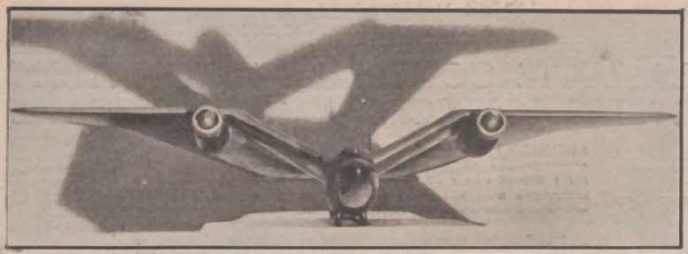
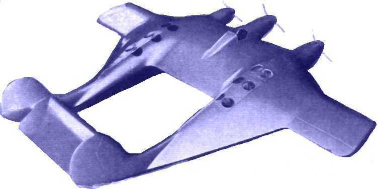
A dramatically lit model of the Willoughby 8A project that appeared in the contemporary French "Ailes" magazine. It shows a gull wing with wing extensions that tapered in a "V" to meet at the tail.
Other photos of the 8A model show the layout in greater detail. It featured the raked-forward windscreen which was then in fashion among aircraft designers.
You can see that this design offered very little space for passengers and cargo relative to the airframe's large size. At around that time, lots of aircraft companies in the USA announced they were working on new airliner designs with pressurised cabins that would allow them to fly "above the weather" and offer passengers a smoother and more comfortable experience. In the UK, the British government would end up subsidising the designs of the Fairey FC1 and Short S.32 pressurised airliners to try to catch up with the Americans. So it must have been obvious to Willoughby that to stand a chance of future success, any new design would need to carry more passengers and accommodate them in a pressurised cabin if possible. Willoughby's solution was to drop the gull-wing aspect of the design and have parallel booms that would be big enough to double as passenger cabins.
Delta F (8)
To validate this new design, it was felt necessary to build a small flying demonstrator. Willoughby's method of naming this demonstrator got increasingly complicated. It seems to have been called the Delta 8, Delta 8AF or 8F in the design stage but was renamed the Delta F when it was registered. Early diagrams of the project show a very different layout to how the final aircraft turned out, with engines suspended under the wing on struts and the booms tapering towards each other. For ease and quickness of construction, it was to be built of wood. It had accommodation for a pilot and single passenger behind the pilot, both in a central "pod", and was to be powered by two American Menasco C-4 Pirate engines, each of 128 horsepower. It had a fixed, 3-point tailwheel undercarriage. Willoughby turned down a quote from the de Havilland company to build the Delta F. Instead, he leased part of a hangar at Witney airfield, west of Oxford and had construction overseen by the resident Witney Aeronautical College. The Delta F made its first flight at Witney on the 11th of March 1939, flown by Captain Archibald Norman Kingwell. Published details of the testing of this aircraft seem to vindicate everything that had been hoped for in the design. It apparently had viceless flying characteristics and a surprisingly high performance on its tiny engines. Most importantly it allowed a high payload to be carried for a low structural weight of the aircraft itself. On the 9th of May, the air correspondent¹ of The Times was taken for a ride in the Delta F and the following day his approving review of its flying qualities appeared in the newspaper. With the name "St Francis" painted on the nose and registration G-AFPX, the aircraft was shown off at the Royal Aeronautical Society's garden party at Heathrow (then a tiny airfield) on Sunday 14th May 1939, again piloted by Captain Kingwill.
You can see a video of the Delta F in flight on YouTube at
<this link>.
<this link>.

The Delta F at Heston.
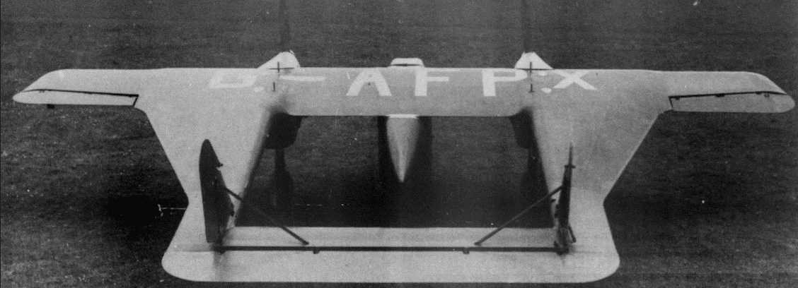
The Delta F seen from behind and above, showing the form of the Willoughby's "side-wings".
The Delta F seen from behind and above, showing the form of the Willoughby's "side-wings".
The Delta F was designed only as a demonstrator and was never intended to be put into production itself. The view from the cockpit was obstructed by the two engines on either side and the positioning of the tail-wheel in the middle of the tailplane might have led to issues if a bumpy landing was made. However, flight testing did show a flaw in the handling of the aircraft; the Delta F had to make its approach for landing at quite a high speed (60 mph, 97 kph) because of the incidence of the tailplane. It was recognised that if the aircraft could be given a variable incidence tailplane (so that it acted like a flap) the approach speed could be cut and the already short landing run reduced considerably.
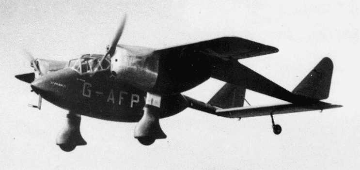
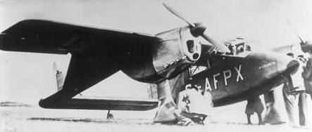
The Delta F in flight. Notice that in this image it does not have spinners on the propellers. Also note the undercarriage legs extended when not compressed by the weight of the aircraft on the ground, exposing an area of a different colour (silver/white?).
It was the looming war that made Willoughby press ahead with increased speed on his airliner project. It was unlikely that there would be much support in Britain for a new airliner, what government finance there was being directed at the Fairey FC1 and Short S.32 pressurised airliner projects. In the prevailing business climate, it was natural for Willoughby to look to the USA, the only country where, in the late 1930s, unsubsidised airliners were commercially viable. He seems to have made contacts there and he sounded out his workforce about the prospects of moving their entire operation to the USA. To gain funds he would have needed to have the Delta F flown for evaluation by other pilots. However, rather than fit the variable incidence tailplane that had been planned, a stop-gap solution of a trim tab on the elevator was thought sufficient. This meant the tailwheel on the tailplane could be kept, since a variable-incidence tailplane would have required twin tailwheels, one on each boom. The trim tab was fitted in early July. Captain Kingwell had only been contracted for the first 5 hours of flight testing and this had now expired, so Willoughby asked the owners of Witney airfield if they could suggest someone to act as test pilot. They in turn asked Hugh Olley, an instructor of the Whitney & Oxford Flying Club, if he would do a test flight of the Delta F on one of his days off from instructing. On the 10th of July 1939, Olly took the Delta F up for a one-hour flight without mishap. Olley then landed and Willoughby went aboard as a passenger (maybe this was the first time he had flown in his creation). Thirty minutes into this second flight the Delta F crashed close to the village of Caulcott near Middleton Stoney in North Oxfordshire, killing both Willoughby and Olley. Tragically the Air Ministry investigation into the crash found that the mechanical "stops" on the elevator tail trim had been omitted after the modification and this was assumed to have caused the crash.²
Willoughby Delta F.
So ended the life of the brilliant Percival-Nesbit Willoughby. With no designer and no aircraft to demonstrate the company folded and became only a tragic footnote in British aviation history.
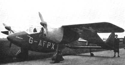
Another view of the Delta F. It had a dull red (maroon?) colour scheme with natural metal engine cowlings and white registration letters with thin black borders. The cockpit framing was silver, the props spinners were probably the same red colour as the fuselage. The propellers may have had a natural wood finish.
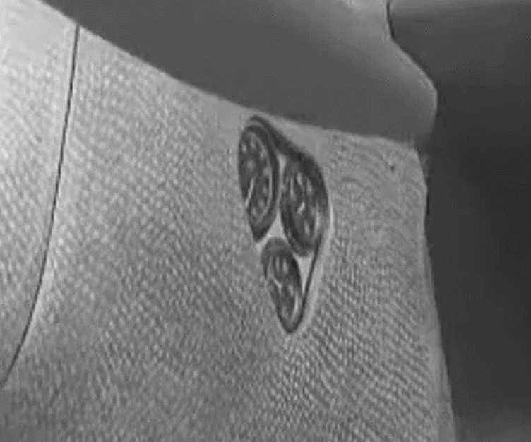
Like a lot of small, twin-engined designs of the 1930s, the Delta F had its engine instruments mounted on the sides of the engine cowlings where they could be easily seen by the pilot. This saved space on the cockpit instrument panel and avoided long wiring and piping runs from the engines. Notice the curious "hammered" effect on the metal engine cowling panels.
Like a lot of small, twin-engined designs of the 1930s, the Delta F had its engine instruments mounted on the sides of the engine cowlings where they could be easily seen by the pilot. This saved space on the cockpit instrument panel and avoided long wiring and piping runs from the engines. Notice the curious "hammered" effect on the metal engine cowling panels.
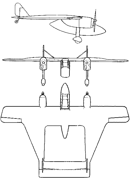
Delta F plan
Delta F Specifications
Max speed; 183 mph (294 kph)
Cruise; 165 mph (265 kph)
Landing Speed: 60 mph (97 kph) as reported by Captain Kingwell after the first flight. The air correspondent of The Times recorded it as 55mph (88.5 kph).
Span 34ft 6 ins (10.51 m)
Length: 26 ft 1in (7.96 m)
Max speed; 183 mph (294 kph)
Cruise; 165 mph (265 kph)
Landing Speed: 60 mph (97 kph) as reported by Captain Kingwell after the first flight. The air correspondent of The Times recorded it as 55mph (88.5 kph).
Span 34ft 6 ins (10.51 m)
Length: 26 ft 1in (7.96 m)
The Delta 9 Project
If Willoughby had lived to build his Delta 9 airliner what would it have looked like? An article in Flight magazine from February 1939 gives a lot of details. It would have been powered by three liquid-cooled engines in the 1,000 hp class (the Rolls Royce Merlin would seem the obvious choice). Two pressurised cylinders would carry the passengers, 18 in each, to give a total of 36 (another source mentions an alternative arrangement of 10 passengers in each cylinder in an overnight "sleeper" arrangement with bunks). Each pressurised cylinder would be in a boom in the aircraft and be linked to each other, and the pilot/navigators compartment, by an emergency unpressurised passageway in the thickest part of the wing. Early versions would likely have been built with no pressurisation for the pilot/navigator compartment. The crew (except for one steward in each passenger compartment) would have had to rely on oxygen masks and risk the dangers and considerable discomfort of unpressurised high-altitude flying. The reasoning for this approach was that the main problem of keeping pressure inside a compartment was the efficient sealing of the holes required for the mechanical linkages for the aircraft controls. If you only pressurised the passenger compartment you did away with this complication (The contemporary Fairey FC1 was certainly designed to initially have only the passenger compartment pressurised). Advances in technologies developed during the war (on the Wellington V and VI high altitude bomber and Spitfire VI and VII high altitude fighter) solved the problem of sealing control linkages. Each passenger cylinder had its own set of retractable air-stairs, toilet, small galley and steward. Because each compartment was buried in a tail boom there was nowhere to put traditional windows for passengers to see out, although there were 6 circular "skylights" in the roof of each compartment to let in light. To give the passengers a view of the ground it was hoped to use a camera obscura device to project an image from the outside of the aircraft onto the table-tops of the passengers. Top speed was hoped to be in excess of 300 mph (483 kph) with a cruising speed of 255 mph (410 kph). A range of 4,500 miles (7,242 km) was hoped for, enough to enable transatlantic flights.
Model of the Delta 9. Note the "skylight" windows above each of the two passenger cabins in the booms
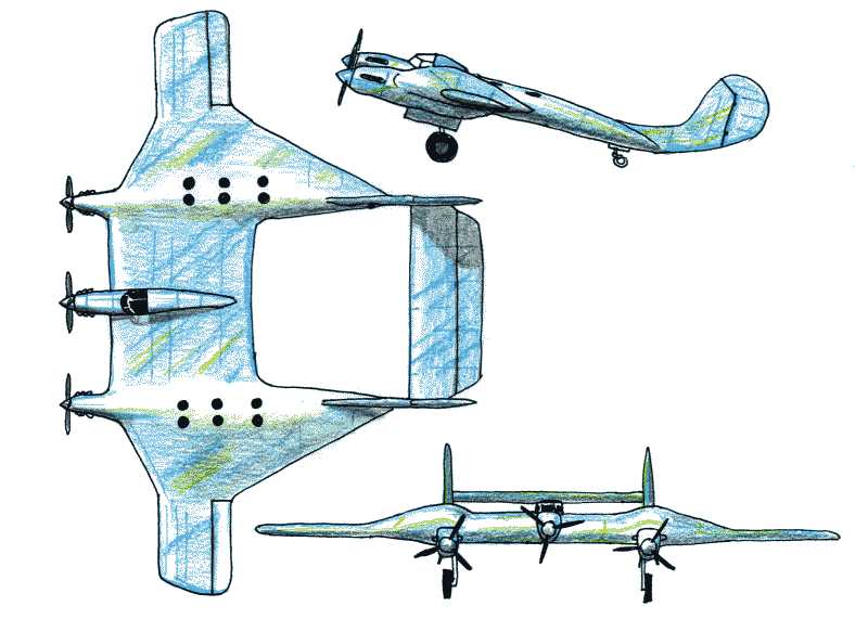
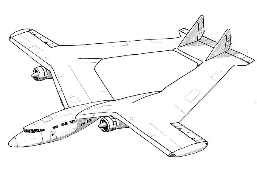
Above is a rough sketch of the Delta 9. Each boom contained a cylindrical pressure cabin for 18 passengers (36 in total). Each cylinder was served by its own set of stairs that retracted into the boom and each had a toilet, galley and steward. The two cylinders and the crew compartment were linked by an emergency unpressurised access tunnel at the thickest part of the wing section. It is not at all unlikely that the crew compartment might not have been pressurised, at least in early production examples, with the pilot(s) and navigator using oxygen masks and enduring the dangers and discomforts of high-altitude flight.
WHAT IF?
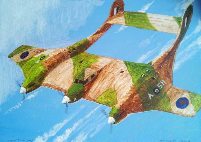
I've painted the projected Delta 9 airliner as if it had been pressed into service by the RAF during the war, (imagine it carrying high-value passengers and parts to Malta or ball bearings from Sweden).
Assuming there had been no crash of the Delta F and Willoughby had lived, and that his backers in the USA had come up with the funding, then it's possible to envisage a crash programme to set up a production line in America, perhaps aided by an existing manufacturer. Whereas Britain stopped all civil aviation development and production at the outbreak of war the attitude in the USA was the opposite. After Pearl Harbour the Americans realised to fight a global war you need as many transport aircraft as possible, so production and development were accelerated. An aircraft like the Delta 9, with the possibility to outrun and outclimb long-range interceptors, would have had a certain amount of appeal for the higher-risk transport links in the Pacific and Mediterranean. Perhaps with Packard-built Merlins, the Delta 9 might have proved a welcome addition to the Allies' transport fleet and gone on to have a useful role after the war into the early 1950s and the advent of jet airliners. Could the rectilinear wing have lent itself to applications with jet engines? Would a rectilinear wing be useful on a modern UAV? Now there are a couple of thoughts!
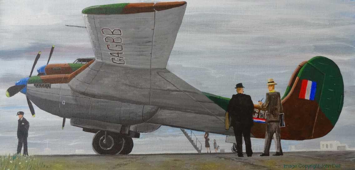
The projected Delta 9 airliner: Painted as if it had replaced the Douglas DC3 on the ill-fated Flight 777.
One British aircraft company might have taken note of Willoughby's work. During the war, Arthur Bage chief designer of the Percival Aircraft Company, schemed a huge transport aircraft (the Percival P35) that incorporated some of Willoughby's ideas. It was to have had either four or six Bristol Centaurus engines with two huge tail booms to accommodate troops or passengers. The booms were to be blended into the wings in the same way as the Delta 9. The centre wing section was to be expanded into a huge Burnelli-style wing profile fuselage to hold vehicles and freight loaded by a ramp from the rear. The crew were to be accommodated in a pod that extended in front of the centre section in the manner of the Burnelli CBY-3. The project never got beyond the initial design stage.³
Notes:
¹ The air correspondent articles in The Times were written anonymously. According to this webpage by Brett Holman, there seem to be two possible contenders for the post in 1939, E. Colston Shepherd or Oliver Stewart.
² A two-part article by Peter Davis, in the Spring and Summer 2021 edition of Air-Britain's Aviation World Magazine sheds new light on Willoughby's projects and highlights his frustrations on getting them into production and the limited budget he was operating on. One sub-article where Paul Jackson asked two experts to evaluate the Delta F with a modern understanding of aerodynamics, speculates that the true reason for the crash of the Delta F might have been a design flaw (which might have been alleviated if the planned variable-incidence tailplane had been fitted). Another sub-article by Paul Jackson gives a biography of Hugh Olley, showing he was not the principal test pilot of the Delta F (as reported in other sources) and that Olley only flew the Delta F on the day of the crash and with no previous experience as a test pilot, he would have been ill-equipped to respond to the situation he found himself in. I strongly recommend anyone interested in the Willoughby Deltas to read these articles.
³ For details of the Percival P35 see Chapter 6 of John Silvester's "Percival & Hunting Aircraft" ISBN 0 9513386 0 9.
Sources:
"Mr Willoughby and his Deltas": Parts 1 and 2, by Peter Davis in the Spring and Summer 2021 editions of Air Britain Aviation World magazine. "A Designed-in Accident?" and "Hugh Olley - Britain's Forgotten Test Pilot" both sub-articles by Paul Jackson in the Summer edition.
"First All-Wing Aeroplane - Flight Trials": A short article in The Times newspaper on the 10th of May 1939 by the anonymous Times Air Correspondent¹.
"The Willoughby Delta": A 5-page article by Arther Orde-Hume in the July 1981 edition of Aeroplane Monthly magazine. This article suggests that the demonstrator G-AFPX was first called the Delta F and then had its name changed to the Delta 8, the opposite to that given in Peter Davis' article in Aviation World magazine. Davis seems to have access to original documents from Willoughby, and says the official registration of the aircraft listed it as the "Delta F"; so I have gone with the demonstrator being called the Delta F on this webpage. Arther Orde-Hume also covers the Willoughby Delta in his extensive reference book " British Light Aeroplanes" published in 2000 (ISBN: 1 870384 76 8).
"British Civil Aircraft 1919-1959": By A. J. Jackson Published by Putnam (Vol 2 page 463).
"Delaying the stall": An article in Flight magazine, Feb 9th 1939.
Links:
Wikipedia article on the Delta F
Report of the Crash of the Willoughby F on Aviation Safety Website.
Wikipedia article on the Delta F
Report of the Crash of the Willoughby F on Aviation Safety Website.

No Ads, No Cookies, No AI generated content.