Dinger's Aviation Pages
The Fairey Hendon
night-bomber
and its projected developments.
Revised in May 2025 with information supplied by
Matthew Willis
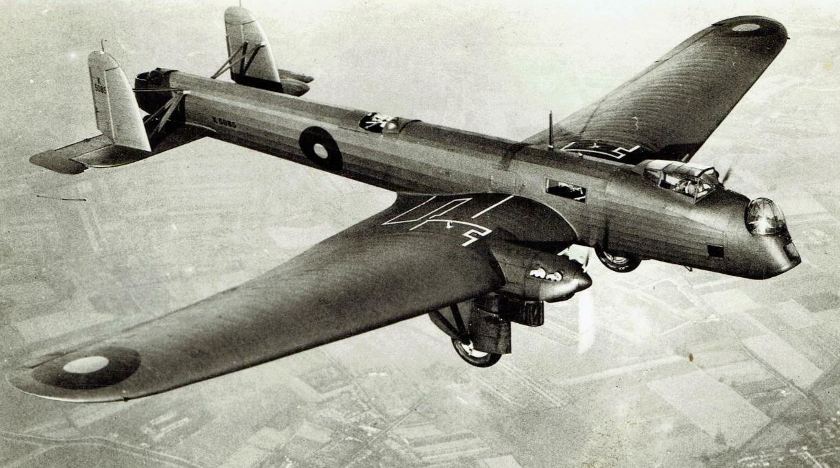
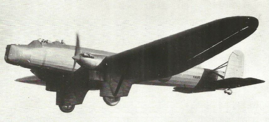
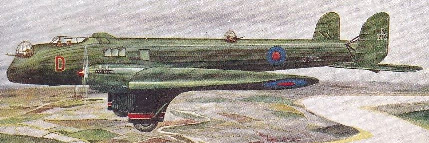
Fairey Hendon in flight. Note the white markings on top of the wing; these outlined the panels that gave access to the bomb cells and fuel tanks. A small door on each side of the fuselage gave access to the top of the wings for maintenance.
When the Fairey Aviation Company first flew their revolutionary Fox biplane bomber in 1925 they gave thought to using the prototype to gain the world distance record. Nothing came of this plan directly but the Air Ministry must have been intrigued by the possibilities because in 1927 they asked Fairey to design an aircraft specifically to gain that record. This brought forth the Fairey Long Range Monoplane, two of which were built. The first of these flew in November 1928 and it made the first non-stop flight to India in April 1929 but tragically crashed during an attempt on the distance record in a flight to Cape Town in December 1929. The second Fairey Monoplane succeeded in gaining the record with a flight to Walvis Bay in South West Africa (modern Namibia) in October 1933.
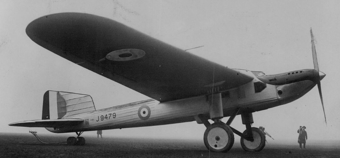
In designing the Hendon, Fairey capitalised on the technology they developed to build the huge, internally-stressed, monoplane wing for their record-breaking Long Range Monoplane (seen above). Little did they know, that in only a couple of years, that technology would be made obsolescent by new, stressed-skin techniques.
The thick monoplane wing that Fairey were developing for their long-range machine seemed to have a lot of scope for further development. So, in parallel with the Long Range Monoplane, they designed a twin-engined aircraft for the Air-Ministry B.19/27 night-bomber specification of 1927. Initial studies had conceived an aircraft with folding wings to be more easily accommodated in the hangars of the period but the design evolved into a larger aircraft. When it emerged from the factory for its first flight in November 1930 the prototype carried a pilot in an enclosed cockpit, a bit of a novelty at the time. To ensure a good view of the ground to judge landing, the cockpit was offset to port (like the cockpits in the later Sea Vixen and Canberra B8 jets). There was a wireless operator's position in the fuselage behind the pilot and a chart table and folding seat for someone to carry out navigation duties below and to the side of the pilot. There were three gun positions, one each in nose, tail and dorsal positions; only the tail position would be crewed during night-time missions, and the other two positions would only be manned if enemy fighters were sighted or the aircraft was caught in searchlights. The tail and dorsal gun positions were accessed by metal catwalks suspended in the framework of the fuselage. The nose gun was above a bomb aimer's position. The aircraft was powered by two Bristol Jupiter radial engines enclosed in some of the first NACA cowls to be used on British aircraft. Fairey had hoped to use the new Bristol Pegasus radial engine on the new aircraft, but none were available in time. The Hendon had its mainwheels enclosed in "trouser" fairings but the engines were located inboard of these when initially built.

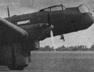
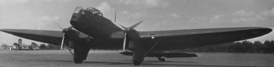
The Fairey Hendon prototype in its original configuration with Bristol Jupiter radial engines enclosed in NACA cowlings. Note the engines are inboard of the main wheels in their trouser fairings. Those heavily dented fairings look more fragile than those on the production aircraft. There looks to be very little gap between the tips of the propellers and the fuselage.
The prototype K1695 did taxying tests on 17th and 18th of November 1930 and then on the 20th of November took short test hops into the air before taking to the air properly on the 25th of November 1930. Testing continued until 31st of March 1931 when one of the engines failed during flight, in the subsequent emergency landing the prototype overshot and crashed, fortunately, there were no casualties.
Fairey decided to salvage what they could of the prototype and rebuild it incorporating improvements, accepting the increased timespan that would involve. During the initial testing, the airflow around the cowled radial engines was suspected of causing a disturbed airflow over the tail and so when the prototype was rebuilt it was given Rolls-Royce Kestrel water-cooled engines instead. These were installed further out on the wings, directly above the trouser fairings of the undercarriage. The wireless operator's position was provided with windows on both sides of the fuselage. The enclosed cockpit canopy was also removed at this time, leaving only a windscreen (although it seems the option of refitting a canopy was retained) and a second open pilots position with dual controls was installed in tandem. The rebuilt aircraft did not fly again until November 1931. At first, a finned radiator mounted on the top surface of the wing was tried, but this did not work well, so underslung radiators were fitted instead. It was found that with the new Kestrel engines, the prototype was some 7 mph slower than with the original Jupiter radial engines. The rebuilt aircraft also incorporated "wash-out" on the wings to make the stall start at the wing root, giving some feedback to the pilot and ensuring the ailerons stayed effective until touchdown was achieved. The prototype was initially rebuilt with the same style of rudders it had before the crash, but at some stage their profile was altered to have straight trailing edges rather than the curved ones of the original design.
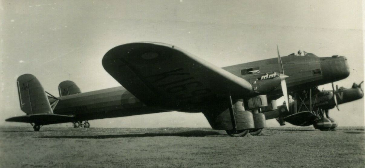
Fairey Hendon Prototype K1695 with a Handley Page Heyford biplane behind, the aircraft that secured the B.19/27 order. Notice the extensive bracing struts needed on the tail and the strut from the wing to the undercarriage .
A number of companies had prepared designs for the Air Ministry specification. The Avro 613, Bristol Type 108 and Hawker B.19/27 were all biplanes and were all rejected at the design stage. The Air Ministry had agreed to pay for the building of three prototypes, The Vickers Type 150 biplane, the Handley Page HP 38 "Heyford" biplane and the Fairey monoplane. Vickers also used their own money to modify an existing Vickers Virginia bomber (J7130) to see if it could meet the performance targets of the specification (it didn't). The Vickers Type 150 was completed first and was evaluated in December of 1929, but was rejected. It was then modified (at Air Ministry expense) into the Type 195 "Vanox" and then into the Type 255, none of these configurations found favour with the Air Ministry. The prototype Fairey Hendon monoplane took part in competitive trials at Martlesham Heath in early 1932 against the Handley Page "Heyford". The Air Ministry ended up ordering the Handley Page Heyford bomber. This is often presented as a lack of vision by the Air Ministry, rejecting a modern monoplane design in favour of an "old-fashioned" biplane. However, this is a view clouded by modern prejudices and preconceptions. In performance terms, there was little to choose between the Fairey monoplane and the HP Heyford. They had about the same top speed (depending on which mark of Kestrel engine was fitted to both aircraft) and had very similar range and ceilings, but the biplane could lift a greater weight of bombs (2,500 Ib (1,134 kg) normal payload but up to 3,500 lb (1,588 kg) in overload condition). More importantly, the biplane had a much lower landing speed, essential for the small grass airfields the RAF then used. Without the benefit of flaps, the Fairey bomber had a high landing speed (for the time) of 68 mph. This was some 13 mph higher than the Heyford, a crucial difference. With the high accident and casualty rate the RAF experienced at the time, and no prospect of a major war foreseen, it is only natural the Air Ministry should opt for the safer design. This was somewhat ironic since Fairey were a pioneer in the design of flaps and had used an early version of them on some of their WWI designs. The Fairey monoplane might look more "modern" but the metal structure of both the fuselage and wings were covered in fabric, a far cry from the multicellular stressed-skin metal structures that were starting to be built in the USA for commercial airliners. The internal bracing, needed to give the Hendon's cantilever wing strength, added greatly to the weight of the aircraft and dictated a very thick wing. Most of the Hendon's structure had to be built of steel for strength rather than lightweight aluminium. This added weight and drag negated any advantage over traditional biplane design. In the late 1970s, I met an old RAF fitter who had worked on the Hendon. He said it was... "Not so much a monoplane, more a biplane with the gap between the wings filled in!"
The Hendon prototype in flight.
There was another issue that mitigated against the ordering of the Hendon; its wingspan of 101 feet 9 inches (31 metres) was too large to fit into the standard "Belfast Truss" RAF hangars of the time that had a maximum door width of 100 feet (30.5 metres). Fairey proposed reducing the Hendon's wingspan to 97 feet 9 inches but the Air Ministry countered that many of their hangars (mostly built in WW1) could not open to their full extent anyway, and even if they did it was still a very small margin to impose. The RAF did have a small number of Type "A" hangars with a width of 120 feet (36.5 metres), but with the austerity measures imposed after the Great Depression there seemed little chance of building more.
Another photo of the prototype, notice the second pilot position added behind the first. The prototype was continuously modified and almost every photo of it shows some change in configuration.
But the Air Ministry did like many elements of the Fairey design and paid for it to undertake tests with an RAF squadron. Then in January 1933, they paid for it to be modernised before an extensive service trial with No 10 Squadron, after which it was modernised yet again prior to another full test at Martlesham Heath in April 1934.
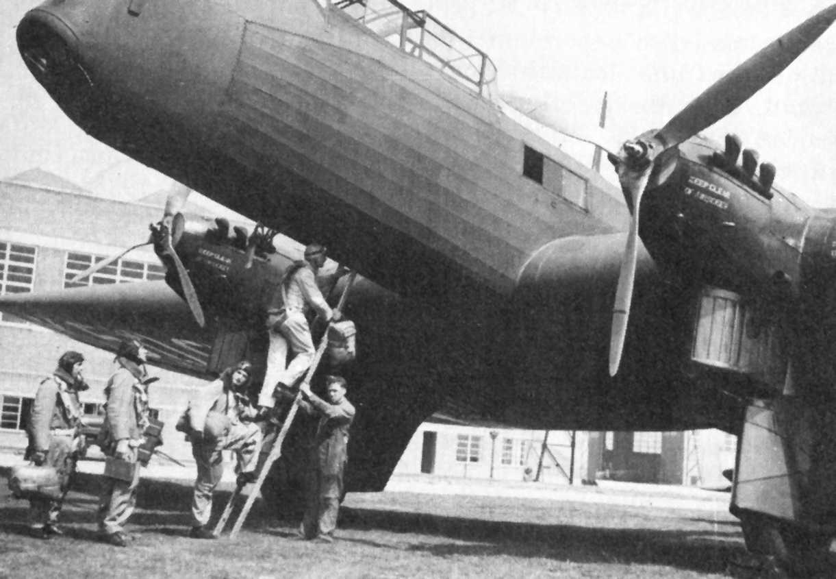
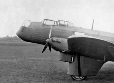
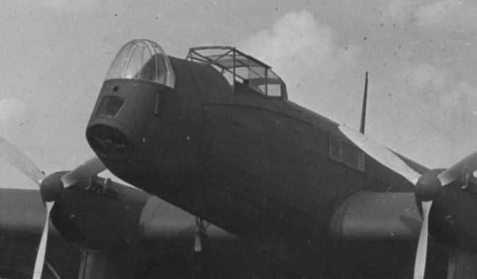
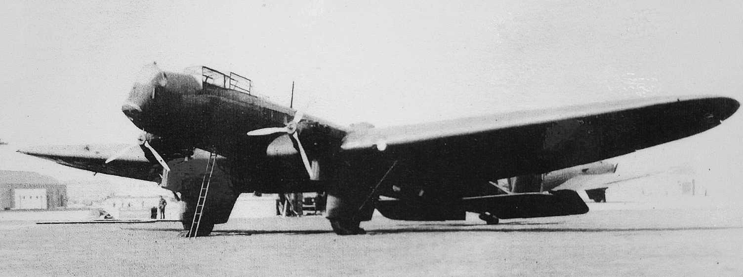
The 4-man crew entering a production Hendon bomber. Note the metal three-bladed propellers. The engines are directly above the main undercarriage wheels. The raised rear canopy shows this to be one of the aircraft modified with dual controls. Entry into the Hendon was by 10-foot ladder or by scrambling up footholds and easing into the rear gunners position! You can see that the Hendon is not suitable for transporting troops, as claimed in contemporary descriptions. Notice the underwing serials of this aircraft are white, unlike the black serials seen in other photos.
Of course, while all this had been going on the political climate of Europe had changed considerably. Hitler had come to power in Germany and although the full scale of German rearmament was still not apparent tensions were growing daily. At the same time developments in commercial aircraft design in the USA had made biplanes look old-fashioned. As part of its rearmament plans, the RAF expanded the size of many of its existing airfields and construction work began on new large airfields better able to accommodate the longer take-off and landing runs of monoplanes like the Hendon. Perhaps more importantly, the money released for rearmament meant the number of "Type "A" hangars with a door width of 120 feet (36.5 metres) had increased and the new type of standard "Type C" hangars being built on these new and extended airfields had a door width of over 140 feet (42.7 metres), more than enough for the Hendon's wingspan. So after the re-evaluation at Martlesham Heath, the Air Ministry issued specification B.20/34 and ordered 14 production aircraft to be called "Hendon", enough to equip a single squadron. The order was placed in mid-1934. This would seem a very low-risk ploy by the Air Ministry to quickly get some "modern-looking" aircraft into the shop window to deter aggression, even though their structure and performance were hardly any different to their biplane contemporaries and they had a very small bombload. The RAF already had much more advanced bombers on order and Fairey had fully investigated the new stressed-skin aircraft designs from the USA and was working on the Battle and P.4/34 bombers. Shortly after this initial order was placed, the revelation of the increased rate of German rearmament panicked the Air Ministry into ordering more Hendons. They went as far as allocating serial numbers for another 61 aircraft (4 dedicated dual-trainers and 57 bombers). This additional order was soon cancelled as the replacement AW Whitley night-bomber promised much higher performance, as did the Handley Page Harrow medium-bomber. Even the single-engined Vickers Wellesley was faster and had a longer range and higher ceiling with a comparable bombload.
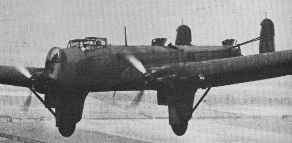
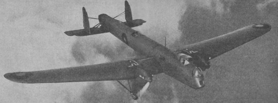
Fairey Hendon in flight, showing the raised rear cockpit for a second pilot and the retractable shields for the dorsal and rear gun positions in the "up" position.
There is another narrative that can be applied to the ordering of the Hendon. In 1934 the international disarmament conference in Geneva collapsed. This was followed by an announcement by the British Government that it would begin increasing the size of its armed forces. This caused a scramble for shares in armament companies, particularly aircraft manufacturers. Fairey had been running at a loss but suddenly found the price of its shares skyrocketing, they jumped from 16 shillings a share up to 1 pound 15 shillings. This meant the company had money in the bank to buy a new factory to build the aircraft it anticipated the Air Ministry ordering. So it purchased the factory at Heaton Chapel near Manchester, which had been built as "National Aircraft Factory No 2" during the First World War and had been used for motor-car production since the war. But what to build in this new factory? The new Fairey Battle was not yet ready for production, so what better than the already-designed Fairey Hendon as a stop-gap? The Air Ministry, tasked with increasing the size of the RAF in short order, would have needed little encouragement in writing specification B.20/34 around the Hendon, especially as it would shortly have airfields and hangars big enough to accommodate them.
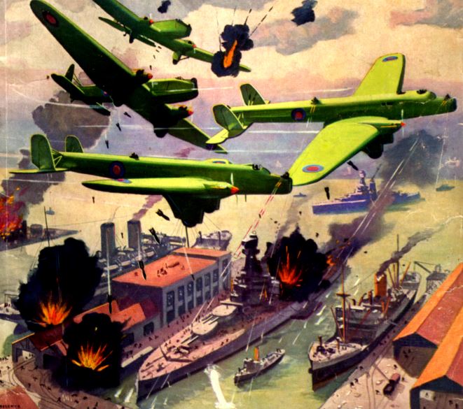
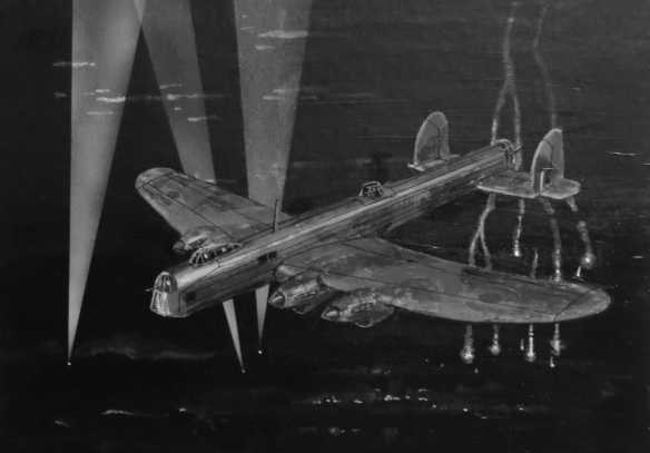
A dramatic painting of Fairey Hendons in action as painted by Frederick Blakeslee for the American "Dare-Devil Aces" magazine in 1936. The painting shows the aircraft in the configuration of the prototype rather than the production machines. He has upgraded the gunners to twin machine guns. The description inside the magazine stressed that the performance of these aircraft was a closely guarded secret.
The production aircraft saw the reintroduction of the enclosed cockpit and this was extended rearwards to give a position for an optional set of pilot controls to be fitted in tandem to the pilot. This position also enabled the person doing the navigation to clamber up and get a view outside (although the front turret and bomb-aiming position would have given a better view). On some of the aircraft, this position was fitted with permanent dual controls and a raised canopy to give a better view ahead. These served as trainers for pilots converting to the type while still retaining full operational capability. More powerful Kestrel VI engines driving metal three-bladed propellers were fitted. Perhaps most noticeably, an enclosed manually-operated front turret was fitted to protect the gunner from the blast of the airflow and an improved slanted and circular bomb aiming window was fitted. The tail and dorsal positions were still open although both incorporated a small retractable windshield to give a bit of protection. Even so, official reports said it was difficult to operate guns in these positions if firing to the side, and gunners quickly became incapacitated by the wind and cold if exposed for too long. In contrast, the front gun turret was praised for its comfort although it was noted that it was difficult to aim the front gun accurately.
Above: the two styles of cockpit. On the left is the normal cockpit, and on the right is the dual-control tandem cockpit with the raised rear portion. The front turret might have doubled as an astrodome for celestial navigation, essential for long range night operations. Although the RAF only began to seriously train in celestial navigation in 1938.
The bomb load and fuel capacity of the Hendon were linked. The Hendon had two large fuel tanks of 250 gallons (1,136 litres) each, accommodated behind the engines in the thick wings with additional small 20-gallon (91 litres) gravity feed tanks directly behind each engine. However, with a full fuel load, the aircraft could not lift the full bombload. If the full bombload of 2,548 lb (1,156 Kg) was to be carried fuel had to be limited to 394 gallons which gave a combat radius of 680 miles (1,094 Km). If the full internal fuel load of 540 gallons was carried then only a reduced bomb load of 1,600 lb (725 Kg) could be carried to a radius of 950 miles (1,529 km). If no bomb load was carried and additional overload fuel tanks were installed in the bomb cells a ferry range of 2,500 miles (4,023 km) was expected. These estimates of range and radius-of-action are "still air" figures with no allowance for headwinds, diversions or search time locating a target.
Fairey Hendon in flight.
The Hendon did not have a central "bomb bay". Instead, it had a series of ten large "bomb cells" that spanned the wing and fuselage between the two engines. Behind those were another six smaller bomb cells in the wing. The Hendon had removable panels on the top of the wing to give access to these bomb cells from above to help with winching the bombs into place. The small bomb cells could accommodate the older 112 lb (50 kg) and 120 lb (54 kg) bombs of WW1 design and presumably the new 100 lb (45 kg) anti-submarine bombs. The larger bomb cells were big enough to accommodate the old WW1 230 Ib (104 kg) bombs and presumably the new 250 lb (113 kg) GP bombs. Only four of these bigger cells had racks able to carry the heavier 500 lb (227kg) or the old WW1 550 Ib (250 kg) bombs. The Hendon also had the provision to carry two of the ubiquitous "light series" bomb racks slightly recessed, one behind each of the two trouser wheel fairings, to accommodate small 24 lb (11 kg) Cooper bombs or incendiaries (up to 4 on each rack).
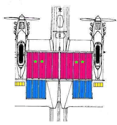
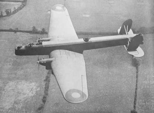
Above: Diagram of the underside of the production Hendon showing the 10 large bomb cells (red) the 6 smaller bomb cells (blue) and the recessed light series bomb carrier racks (yellow). The green asterisk indicates the four larger bomb cells that were capable of carrying the heavy 500 and 550 Ib bombs.
Contemporary and subsequent descriptions of the Hendon usually claim "15 to 20 fully equipped troops can easily be transported". That is a frankly ridiculous statement (although it depends on how you define "easily"). Since an average 1930s male weighed 160 lbs, even 15 soldiers, without any equipment, would have weighed about as much as the Hendon's maximum bomb payload of 2,448 lbs. The primary access to the interior of the Hendon was through a hatch in the nose (see photo above) which required a 10-foot (3m) ladder, or alternately by scrambling up hand and foot holds and tumbling into the rear gunner's position. Once onboard, only a limited area around the pilot, navigator and radio operator positions had a proper "floor". The rest of the length of the Hendon had only a narrow catwalk. Any troops carried in a Hendon would have found it a very uncomfortable ride with an awkward entry and exit, especially if loaded down with weapons and other equipment. They would have had to be thoroughly briefed not to damage the fabric covering the fuselage or touch any of the exposed control cables. The unheated interior of the Hendon would have been very cold in winter or if flown at altitude. It seems the claim that it could accomodate troops stems from a single article in a May 1938 edition of "Flight" magazine where it was observed that the catwalk from the rear gun position was long enough for 15 to 20 troops to stand on. Such a load distribution would have made the aircraft too tail-heavy to fly.
A contemporary postcard illustration of the Fairey Hendon by AFD Bannister. He was usually noted for his accuracy but in this case, he seems to have invented an enclosed turret for the dorsal position (at least no photograph of such an installation exists). Note the pilot and "navigator" in tandem under the enclosed cockpit canopy.
In service, the Hendon would normally be crewed by 4 people (B.19/27 specified a crew of 4)¹. There would be the pilot in the enclosed cockpit. A second pilot, who carried out the duties of navigator, either sat in tandem behind the pilot or at a chart table with a fold-down seat inside the fuselage below the pilot; he would also be expected to go forward to act as bomb-aimer and front-gunner. Then the radio operator sat in the fuselage facing backwards just behind the cockpit. If the aircraft was attacked, the radio operator would go back and take up the dorsal-gun position (the majority of the RAF's volunteer air gunners came from the electrical and wireless operator ground trades). Finally, in the tail was the dedicated tail gunner. On flights of limited duration the pilot himself would take on the duties of navigation and the second pilot's place would be taken by an "air observer" who could man the front gun, be the bomb-aimer and handle charts for the pilot.² On training missions it would not be unusual to carry one or two more crewmen to get extra experience (and bump up their flying pay).
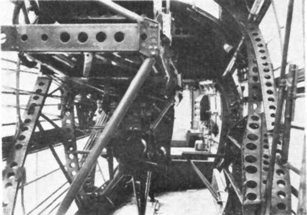
Above is a poor-quality image of the interior of a production Hendon; looking forward from the radio operator's position. The pilot sat on the raised platform on the left, you can just make out part of the instrument panel in front and there is a large control wheel on the left (trimming wheel perhaps?). Notice the foldable seat on the right, it looks exactly like the foldable seat for the flight engineer on the Lancaster of a decade later. There are additional instruments above it on a panel on the fuselage side on the right. Up a step and forward are the front gun and bomb-aiming position. You can see the exposed control cables running along the left-hand side. Hardly a space suitable for the transport of passengers or troops.
The Hendon prototype K1695: rebuilt to production standard (the serial number is visible under the wing on the original photo). The thickness of the wing is particularly evident in this view.
The cockpit canopy of the Hendon can be deceptive; looking at this view in isolation you would swear it was placed centrally on the fuselage.
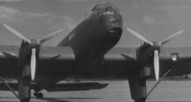
But if you look at this view of the same aircraft from the other side and compare it with the previous image you can clearly see the cockpit is offset to one side. This enabled the pilot to better judge the distance above ground when landing.
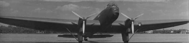
A wider view of the aircraft. Again, the thickness of the wing is evident.
The cockpit canopy of the Hendon can be deceptive; looking at this view in isolation you would swear it was placed centrally on the fuselage.
But if you look at this view of the same aircraft from the other side and compare it with the previous image you can clearly see the cockpit is offset to one side. This enabled the pilot to better judge the distance above ground when landing.
A wider view of the aircraft. Again, the thickness of the wing is evident.
The Hendon was particularly noted for the ease with which its engines could be serviced, with attachment points for platforms to allow easy access. There was provision for a derrick to be attached behind each engine to allow them to be easily winched into and out of position.
The Hendon entered service with 38 Squadron at Mildenhall in November 1936, some 6 years after the first flight of the prototype. The last Hendon off the production line reached the squadron at the end of March 1937. The faithful prototype was upgraded and also served with the squadron. It is interesting to note that Mildenhall was probably the largest RAF airfield at the time, giving ample room for the long landing space required by the Hendons, with their lack of flaps and tendency to "float" down the runway. Mildenhall also had the new "type A" hangars big enough to accommodate the large wingspan of the Hendon and the even bigger "type C" hangars were also being built there. Later the squadron moved to Marham (another airfield recently expanded) and some of the Hendons were detached to form the nucleus of the newly reformed 115 Squadron, but the aircraft were returned to 38 Squadron when 115 received Handley Page Harrows as replacements. The Hendons saw service for only two years, until the end of 1938, when the squadron re-equipped with Wellingtons. During that time only two Hendons were written off because of crashes (both at Marham). One of these (K5094) was an aircraft reported to have been "hijacked" by two groundcrew for a lark; it was fitted with dual controls and crashed because they both tried to control it at the same time. Fortunately, no one was injured.
Fairey Hendon in service.
One would have assumed that the RAF would have been keen to show off its first monoplane bomber. However, the Avro Anson coastal patrol monoplane with retracting undercarriage had already gone into service 9 months beforehand, stealing the limelight. Even as a bomber, it was the only monoplane bomber with the RAF for less than two months, with Handley Page Harrows starting to be delivered in January 1937. In early March 1937, even before 38 Squadron was fully equipped with Hendons, the first of the vastly superior Armstrong Whitworth Whitley night bomber was delivered to the RAF (Bristol Blenheims started to be delivered the same month). In April 1937, Vickers Wellesleys started to join RAF squadrons. When the RAF's annual air pageant was held in June 1937, the Hendons put in an appearance in the mass 260-aircraft flypast but it was the Whitley, Wellesley and Blenheim that starred in the set-piece bombing display.
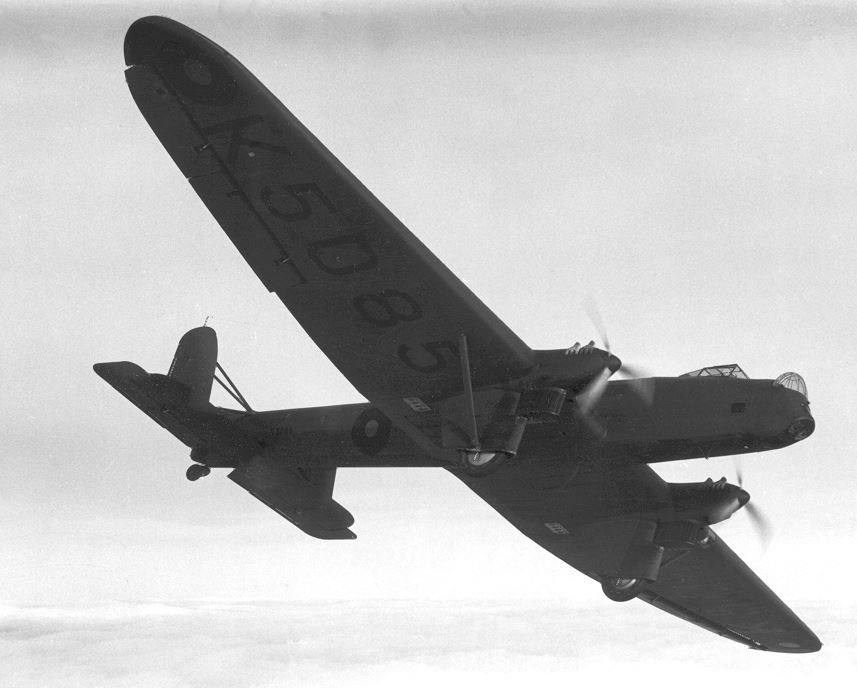
The first production Hendon (K5085) in flight, showing off the all-over "NIVO" finish with "B" type roundels and large black serials under the wings.
Throughout their service, the Hendons were painted overall in a very dark green-grey "Night Invisible Varnish, Orfordness" (NIVO) a colour used for night-bombers by the RAF dating back to World War One. There is no photographic evidence of them ever adopting the disruptive camouflage introduced in the late 1930s. Roundels were "type B" red/blue and small black serial numbers were carried on the rear of the fuselage and rudders. When they were first delivered the production Hendons had large white serials under the wings and white outlines to the bomb and fuel tank hatches on top of the wing; both were later overpainted in black sometime in 1937. Some Hendons carried dull red stripes or diamonds on the undercarriage trouser fairings.
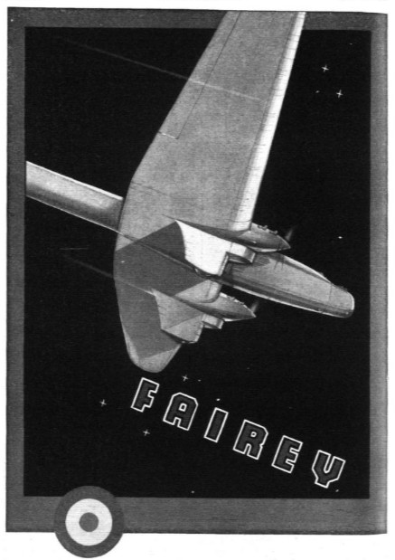
A striking Art Deco style advert for the Fairey Hendon from 1935. It stresses the streamlined form of the aircraft, implying a sense of speed that was not really evident in its actual performance by the time it entered service in late 1936.
After withdrawal from frontline service, the primitive internal layout of the Hendon, with its narrow catwalks and awkward entrance hatch, did not lend itself to transport or "flying classroom" duties. Its lack of flaps would have made the dual-control aircraft unsuitable for use as pilot trainers for the new generation of bombers entering service. So the Hendons were retired to ground-instruction duties. However the structure of the Hendon was already so out-of-date that they were of little use for teaching airframe maintenance, so it seems some of them were stripped of their outer wings and used for a while by No 1 Electrical and Wireless School at Cranwell as platforms to practice fitting, operating and removing radio equipment inside aircraft. It is possible that the Kestrel engines stripped from them were rebuilt and upgraded to Kestrel XXX standard for use in Miles Master trainers (no Kestrel XXX engines were built as new, they were all upgraded from earlier versions). The last flight by a Hendon took place in early January 1939, 8 months before the start of WW2 in Europe. The biplane Handley Page Heyford outlasted it in RAF service; the Heyfords saw service until 1941 as gunnery and bombing trainers and as glider tugs.
Specification (Hendon Mk 2 production version)
Max speed: 154 mph (248 kph)
Cruising speed: 115 mph ((185 kph)
Service ceiling: 21,400 ft (6553 m)
Range and bombload: See text above.
Defensive armament: 3 x .303 Lewis guns. One each in nose, tail and dorsal positions.
Empty weight: 14,032 Ib (6,365 kg) Max weight 20,000 lb (9,072 kg).
Engines: Two Rolls-Royce Kestrel VI engines, variously rated between 455 and 695 horsepower depending on rpm. The authoritative Lumsden book on British aero-engines has them capable of 740 hp for 1 minute at 2,900 rpm and +6 lb/sq inch boost up to 1,000 ft at takeoff.
Serial numbers: Prototype K1695. Production K5085 to K5098. Cancelled order K5768 to K5771 (dedicated pilot trainers) and K6555 to K6612 (bombers).
Dimensions
Different sources give different dimensions for the Hendon's airframe, although the figures for wingspan and height are all within a few inches. However, the most widely quoted figure for the length of the Hendon's fuselage is completely wrong, and not by a small amount, but by 10 feet 6 inches (3.2 metres)! Unfortunately, this is the figure given in Putnam's titles on Fairey Aircraft and British Bombers, so has been regarded as authoritative and has been copied in almost every article, webpage and video about the Hendon. This figure (of 60 feet 9 inches) is simply impossible when measured in ratio to the wingspan on photographs and diagrams of the Hendon (and we can be confident of the wingspan of the Hendon to within a few inches because it is the subject of Air Ministry correspondence about the size of hangar doors).
These are the figures revealed by Matt Willis' research and his access to the official RAF Air Publications (AP) on the Hendon.
Fuselage length (measured nose to tail with tail up) from AP: 71 ft 3 ins (21.7 metres).
Fuselage length on the ground (tail down) from I.D. Huntley's article - see sources below: 69 ft 7 ins (21.2 metres)
Wingspan from AP and Huntley: 101 ft 6 inches (30.9 metres), Air Ministry correspondence about hangar doors says 101 ft 9 ins (31 metres)
Height from AP: 22 ft (6.7 metres)
Height on the ground (tail down) from AP and Huntley: 18ft 8 inches (5.7 metres).
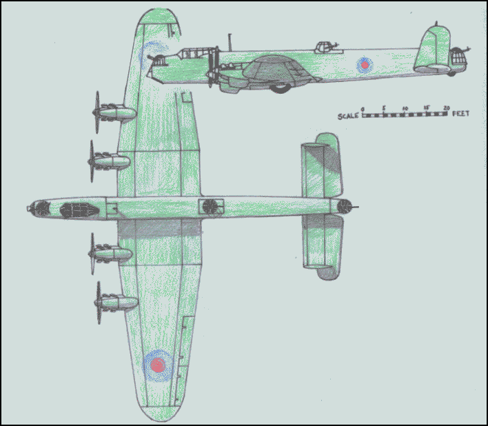
The most widely reproduced plans of the Fairey Hendon are the very basic and poorly detailed small ones found in the Putnam titles (see sources below). These show a window on the port side of the nose that was only on the starboard side of the aircraft. The ratio of the wingspan to the fuselage length is actually correct, at odds with the dimensions quoted in the Putnam books. The February 1974 edition of Aircraft Illustrated magazine had much more detailed plans drawn by I.D. Huntley, albeit at a small scale of 1 cm= 5 feet, to be accommodated in the small format of the magazine. They show the correct layout of bomb cells with 10 large bomb cells spanning the area between the main undercarriage wheels, as detailed in the AP and confirmed in photographs. However, the plans scale out for the fuselage to be about 1 foot undersize and the wingspan to be about 4 feet too narrow. The plans that accompanied Matt Willis' article in the July 2023 edition of Aeroplane Monthly magazine were drawn up before Matt's research uncovered the true dimensions, so unfortunately they repeat the error of getting the fuselage too short. By far the best and most detailed plans of the Hendon can be found in the 3rd-16th December 1982 edition (volume 11 number 14) of Aviation News, drawn by Chris Bowley (the same plans were available via the now sadly defunct Aviation News plans service). These are in 1/72 scale and show the layout of both the early prototype and production aircraft. The fuselage length is spot-on to the figures in the AP, but the wingspan is 1 foot too wide. It only shows 8 large bomb cells under the wings, but the position of the other two under the fuselage are easy to ascertain.
The Hendon 6-stage development programme
Fairey had a history of the progressive development of designs to keep them up to date. The best example of this is the Fairey III series which started during the First World War with the IIIA and evolved through the B, C, D and F and then onto the Gordon and Seal that were still in service at the start of World War Two. When they first designed the Hendon, they were, of course, completely unaware of the revolution in multicellular stressed-skin wing design that would shortly take place (the Northrop Alpha that pioneered this type of design entered service in 1931). So it was natural for them to think of ways the Hendon could be progressively improved to meet future needs. In an article in the February 1974 edition of Aircraft Illustrated magazine, the Fairey archivist ID Huntley described a brochure that outlined the progressive improvement and refinement of the Hendon in 6 stages. Each stage would be an improvement that could be easily introduced on the production line. Unfortunately, the sole drawing that survived illustrates only the final "6th stage" aircraft, a four-engined, low-wing bomber with retractable undercarriage and enclosed turrets. It retains the offset cockpit of the Hendon and seems to be powered by RR Kestrel engines. The drawing does not show if flaps were to be incorporated.
The "6th Stage" 4 engined Hendon development.
At first glance, this design seems amazingly similar to the Avro Lancaster, but appearances can be deceptive. This "Superhendon" still had a heavy fabric-covered airframe, low-powered Kestrel engines (giving only a third the power of the Lancaster's Merlin engines), and manual (rather than power-driven) turrets only armed with a single gun apiece. The bombload quoted was only the same as the Hendon, 2,548 lb (1156 Kg), tiny compared to aircraft like the Lancaster Halifax and Stirling. For deterrence value, it might have looked good in the "shop window" in 1936-38 but, it's hardly an aircraft you would choose to go to war in during the 1940s.
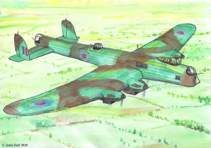
Above and below: What a Stage-6 "Superhendon" might have looked like in service.
NOTES
¹ Some articles, online videos and even Putnam's book "The British Bomber Since 1914" claim that the Hendon was crewed by 5 people. This ignores the fact that the original specification called for a crew of 4 and that the official loading scheme for the production Hendon specified "crew 4 including parachutes". The contemporary "Aero Engineering Data Sheet" also listed the Hendon as having a crew of 4. No doubt on training missions one or two extra air gunners could have been carried to get experience but for its operational night-bomber role only a crew of 4 was required.
² The ranks, duties and training of the aircrew of British bombers were changed considerably in the late 1930s and early 40s. Read "Observers and Navigators" by CG Jefford ( ISBN 978-1-909808-02-7 ) for a full understanding. Or, for a much shorter overview of how the role of Navigator evolved, read this pdf copy of an article from the "Tee Emm" aircrew magazine of March 1946 at <this link>.
² The ranks, duties and training of the aircrew of British bombers were changed considerably in the late 1930s and early 40s. Read "Observers and Navigators" by CG Jefford ( ISBN 978-1-909808-02-7 ) for a full understanding. Or, for a much shorter overview of how the role of Navigator evolved, read this pdf copy of an article from the "Tee Emm" aircrew magazine of March 1946 at <this link>.
LINKS
Fairey Hendon Wikipedia entry (as of May 2023 it had incorrect fuselage dimensions and crew numbers) .
Fairey Hendon on the Aviastar website (as of May 2023 it had incorrect dimensions and crew numbers).
An excellent collection of photos of the Hendon on the "Destinationsjourney" website.
Photo of the first production Hendon under construction with the prototype behind.
George Nixon's webpage covering the Fairey Heaton Chapel factory.
NOTES ON SOURCES
Massive thanks to Matt Willis for sharing information about the Hendon. Matt's article on the Hendon was published in Aeroplane Monthly Magazine's July 2023 edition, in the magazine's big "Database" feature. It's by far the best and most accurate description of the Hendon published. It is accompanied by some great photos of the Hendon, many of which have not seen wide-scale publication before. Unfortunately the plans that accompanied the article get the length of the fuselage too short. The article is currently available to read in full on the Key Aero website at <this link>.
Fairey Aircraft Since 1915: By HA Taylor. Published by Putnam. ISBN 0-370-00065-X. It gives an inaccurate figure for the length of the fuselage of the Hendon.
The Fairey Hendon: A two-part article by ID Huntley (the Fairey archivist) in the January and February 1974 editions of Aircraft Illustrated magazine.
RAF Bomber Command and its aircraft 1936-1940: By James Goulding and Philip Moyes, first published in 1975, reprinted in 2002 by Ian Allan publishing. ISBN 07110 0627 X. The very brief (only a few sentences) interpretation of the events around the ordering of the Heyford rather than the Hendon is at odds with the one you'll find on this webpage. The otherwise excellent colour artwork of the Hendon has only eight large bomb cells rather than the ten the Hendon actually had.
The British Bomber since 1914: By Peter Lewis, published by Putnam. ISBN 0 370 10040 9. It is inaccurate about the number of crew and the dimensions for the length of the Hendon in the appendix are wrong.
Industry and Air Power - The Expansion of British Aircraft Production - 1935-1941: By Sebastian Ritchie, published by Frank Cass in 1997. ISBN 0-7146-4343-2. Has details about the "aircraft boom" and the increase in Fairey's share price.
The British Aircraft Specification File: By KJ Meekcoms and EB Morgan. Published by Air-Britain in 1994. ISBN 0 85130 220 3.
Aero Engineering Data Sheet No 20 - The Fairey Hendon: One of a series published in the late 1930s, contemporary with the Hendon. It lists the correct crew complement.

No Ads, No Cookies, No AI generated content.