Dinger's Aviation Pages
Photos of the wreck of Blackburn Skua L2940 at the FAA Museum, Yeovilton.
The purpose of this page is to illustrate some of the points in my document about the outline of panels and access points on the Blackburn Skua. That document can be viewed and downloaded at this link.
<Click here>
Skua L2940 crashed after an engagement with a Heinkel He 111. An overview of the story can be read on my webpage about Skuas in the Norwegian campaign at <this link>, or you can visit an archive copy of a website devoted to the recovery of the wreck of the Skua at the link below.
<Click here>
In the Fleet Air Arm Museum at Yeovilton, the wreck of the Skua is displayed as if it was still at the bottom of the fjord, being recovered by divers. One wing is supported by straps.
For more general views of the wreck of L2940 as it is displayed at Yeovilton can I recommend this webpage by someone who is a far better photographer...
<Click here>
Click on the small thumbnail images for larger versions.
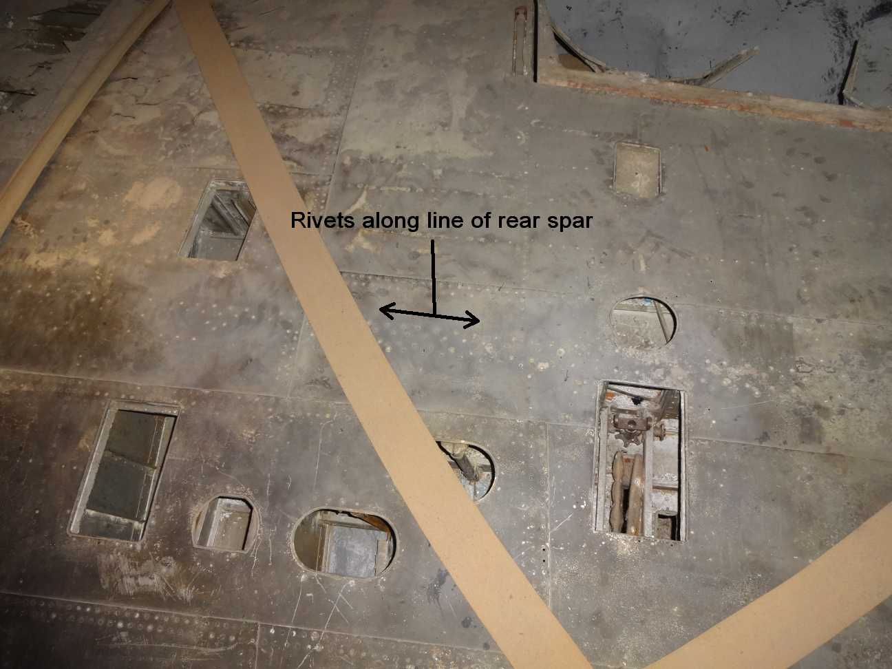
Access panels on top of the port wing. The front of the wing is at the bottom. The bottom two rectangular panels would have been for the machine guns, (the ejector port for spent cartridges can just be seen in the right hand one). Unlikely as it seems, a wartime photo of the guns being reloaded suggest that the ammunition was kept under the two rear rectangular hatches (one of which still has its cover on). This would dictate a somewhat tortuous route for the ammunition belt, through the rear spar.
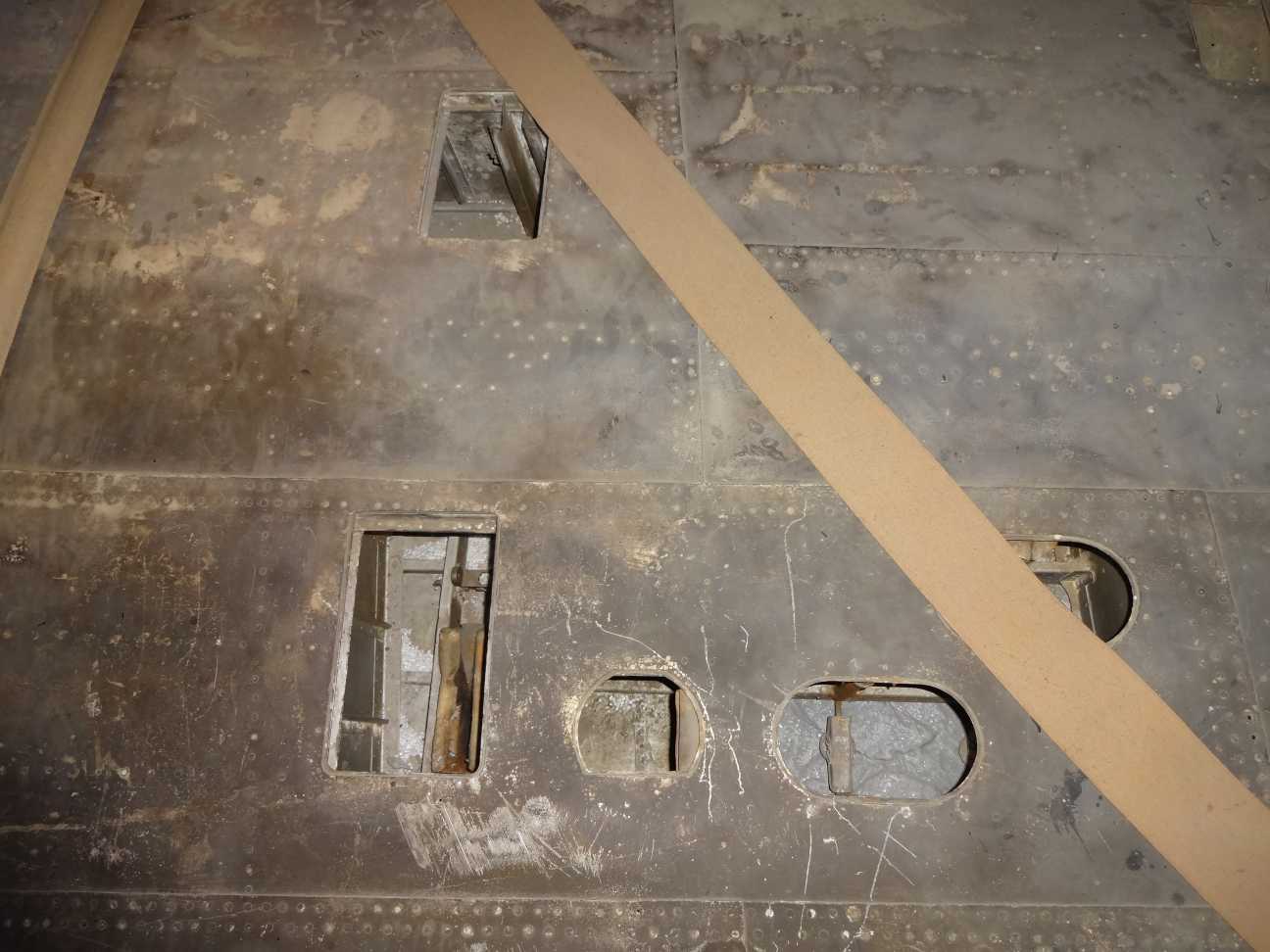
A closer view of the openings.
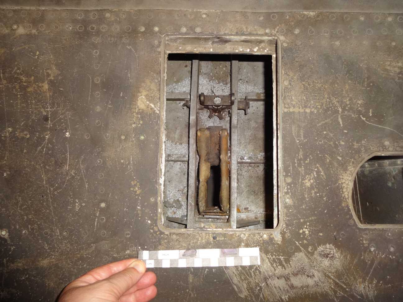
Closer view of one of the rectangular openings. It measures 6 inches by 9½ inches (15.24 cm x 24.12 cm)
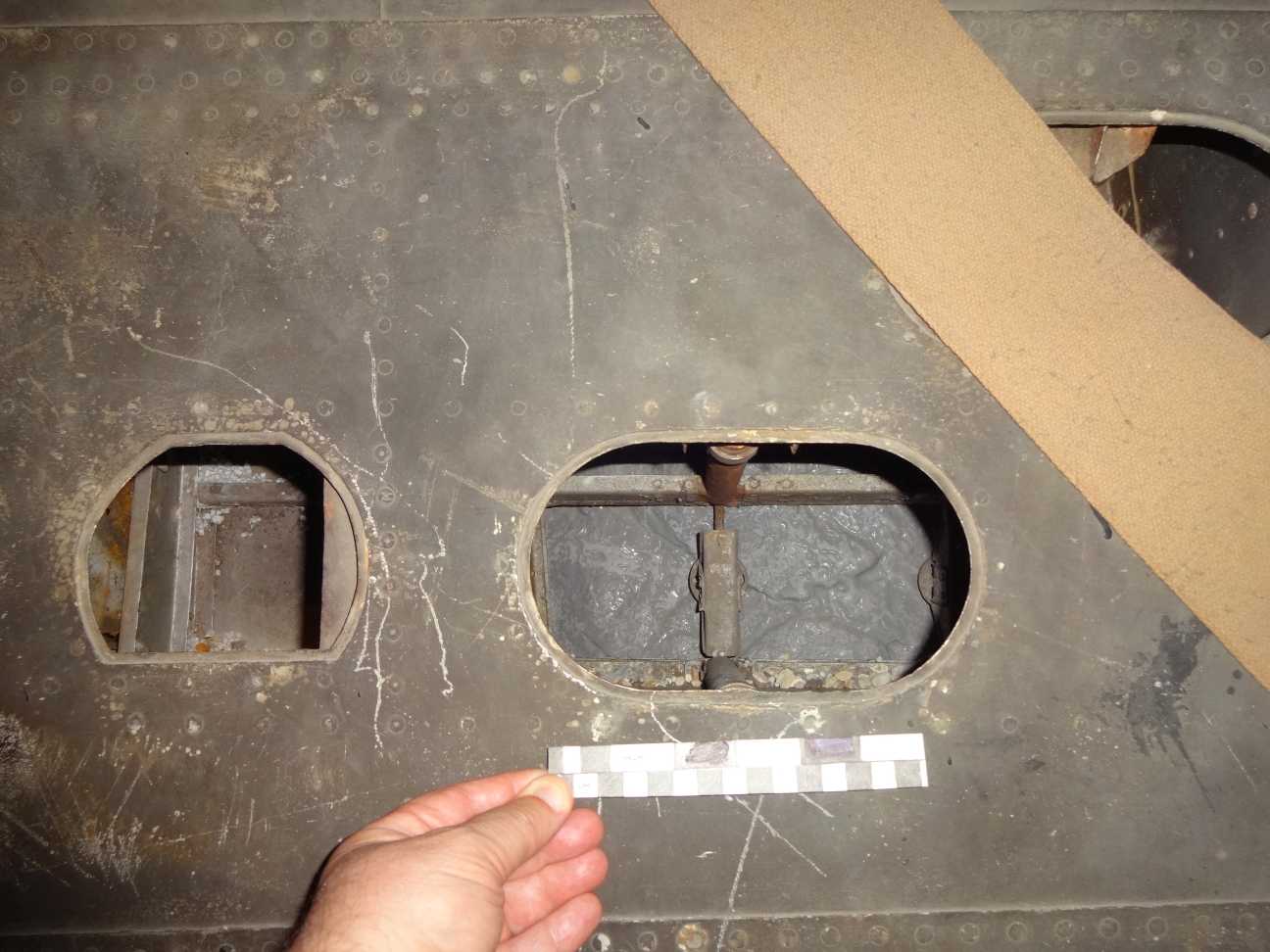
Close up of one of the oval openings. It measures 7 inches by 4 inches ( 17.78 cm x 10.16 cm)
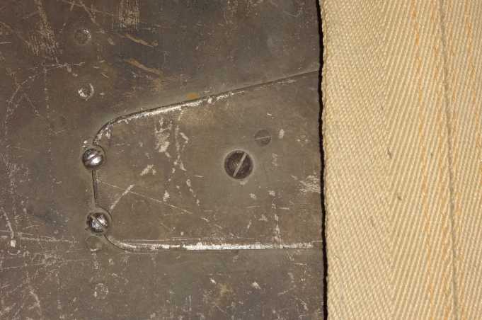
Detail of a small access panel on the upper wing inboard of the guns.
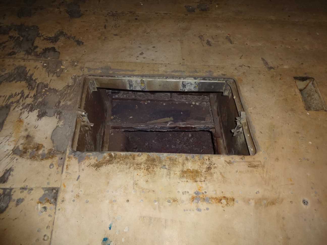
Opening on the bottom of the starboard wing. A similar sized panel on the port wing is associated with a bank of recognition lights on some photos of Skuas.
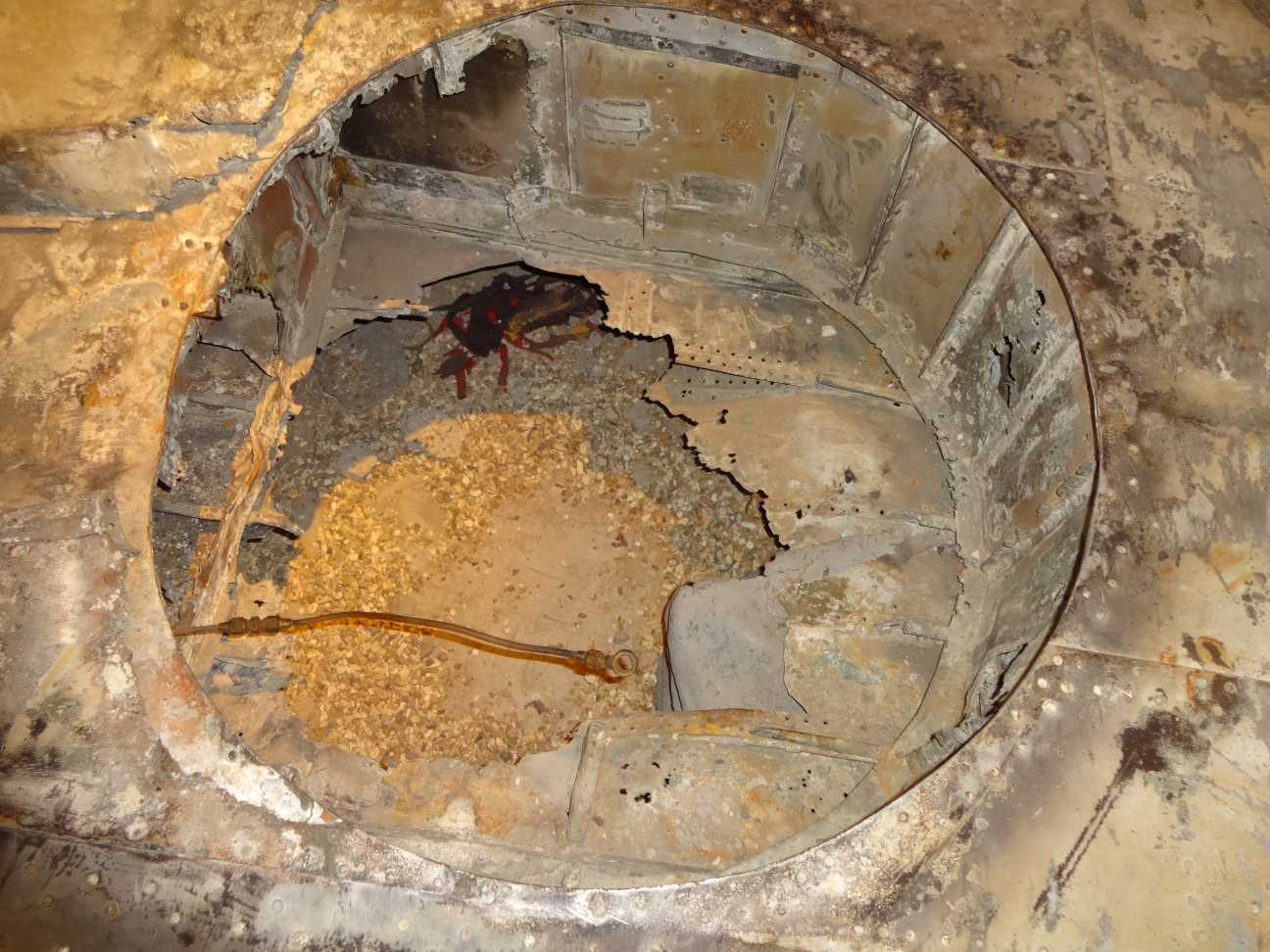
Looking into the undercarriage wheel well. It takes up the whole depth of the wing. The associated recesses for the undercarriage legs are much shallower.
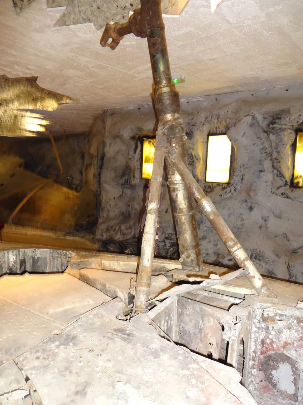
The undercarriage legs for the starboard wing. Notice the heavy domed rivets assocated with the hinges on the wing spar.
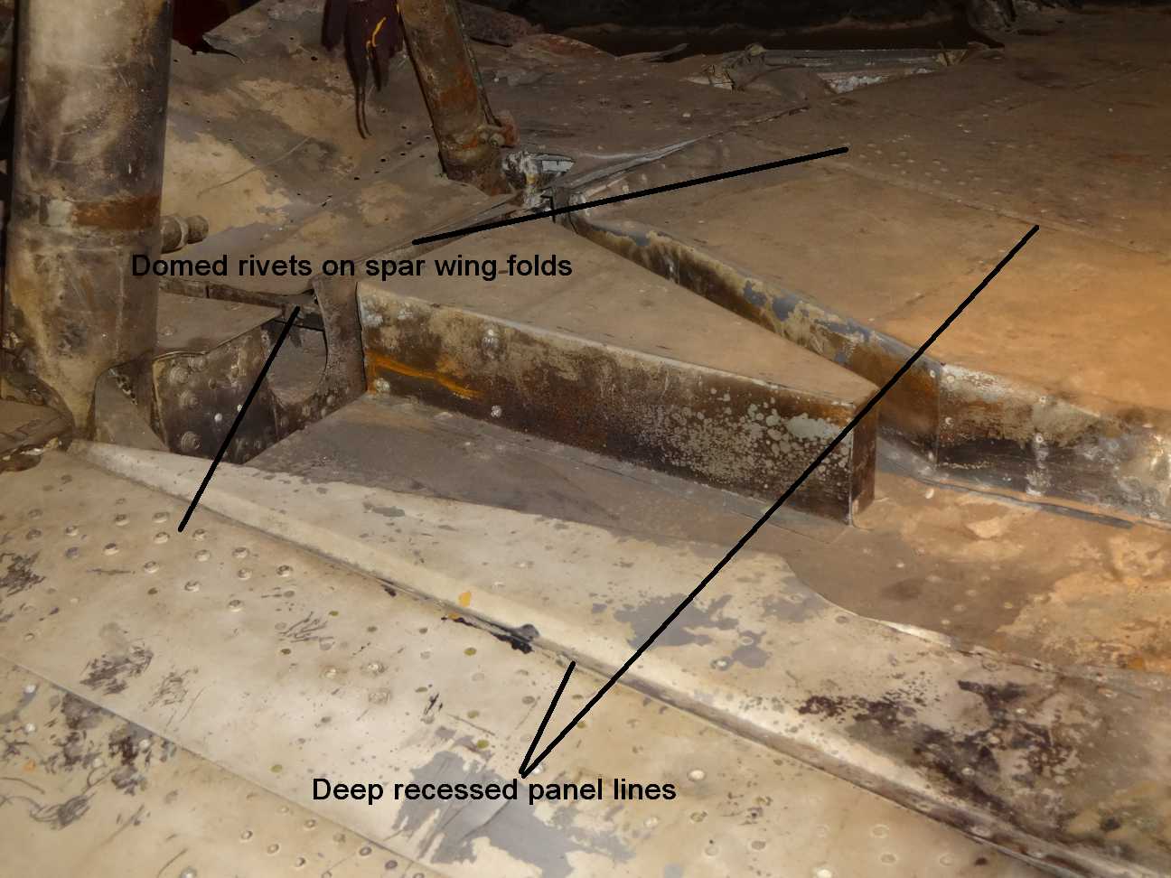
A view of the recess for the undercarrige leg on the starboard wing. Again, notice the domed rivets on the wing spar hinges. Also the two prominent recesses that show up well on photos of the Skua underside.

The two strakes that held the light series bomb rack when it was fitted. They were under both wings (this is under the starboard wing).
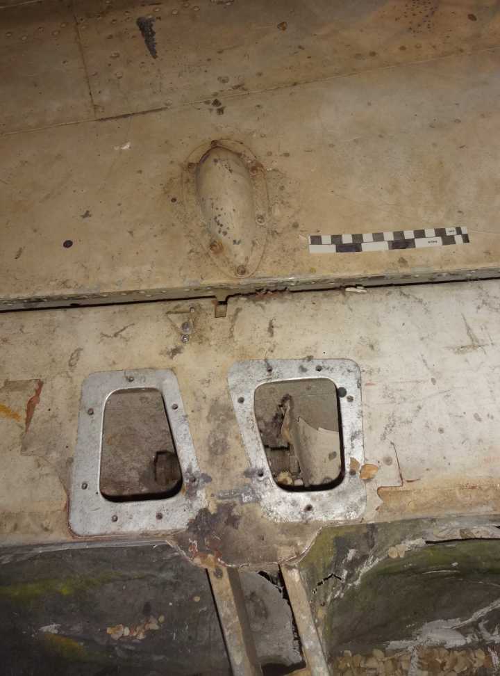
The bulge over the aileron activation lever.
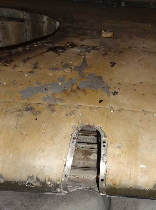
The opening on the wing leading edge for one of the machine guns. It is missing its cover plate which would have left only a small hole just above the leading edge of the wing for the gun to shoot through. Presumably this larger opening was required because the barrel of the gun had to be angled downward when it was shoe-horned into the small opening in the top wing. The gun arrangement of the Skua does look remarkably difficult for maintenance compared to the Spitfire and Hurricane.
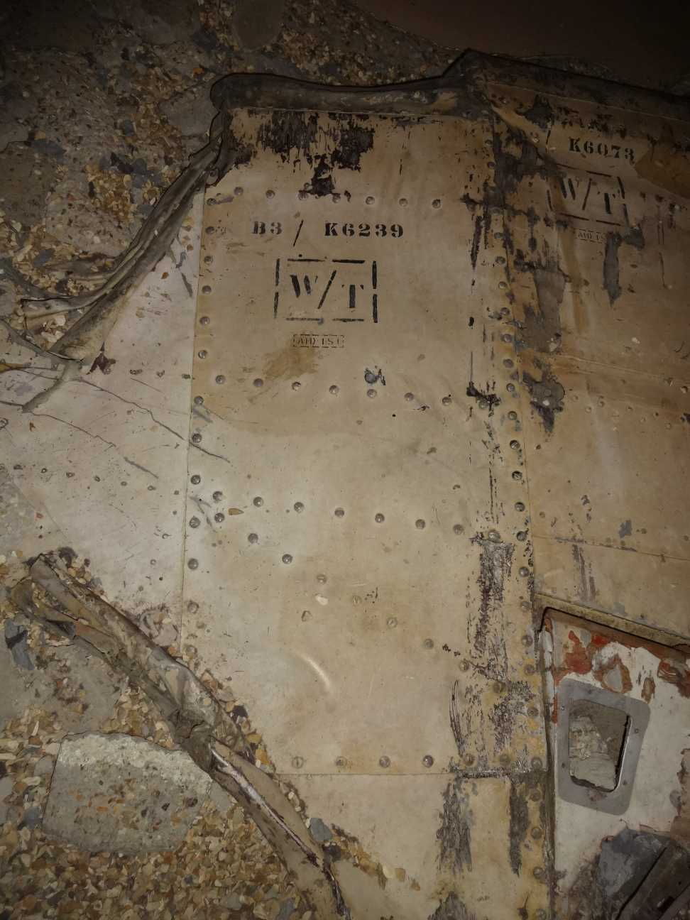
The removable panel under each wing-tip was held in place by a host of dome-headed slotted fasteners (I count 97). It must have taken a while to remove!
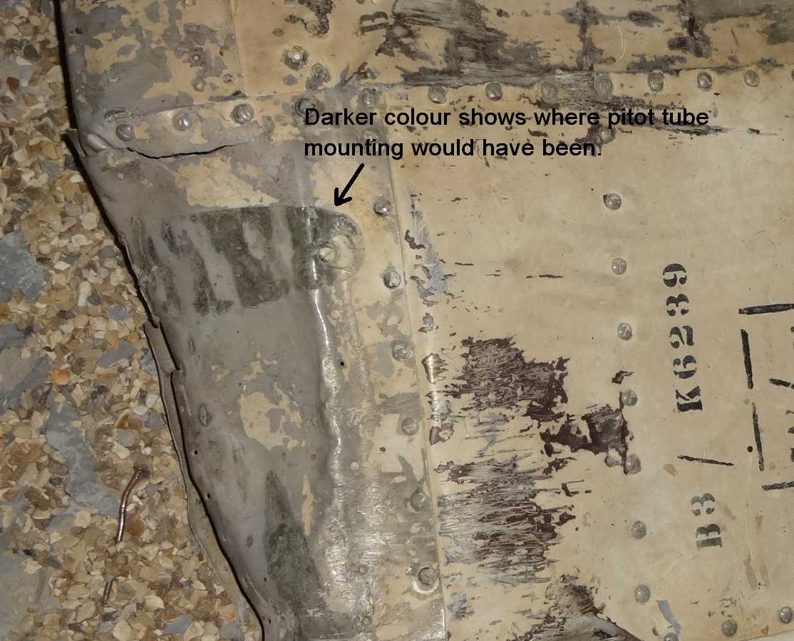
A discolouration in the leading edge of the wingtip shows where the pitot tube was located.
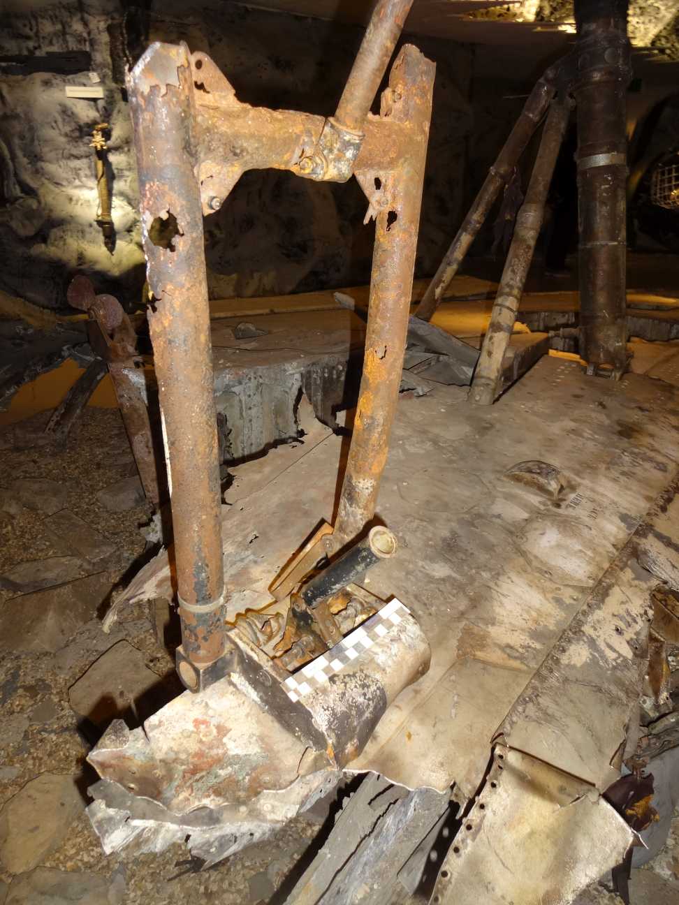
All that's left of the bomb-crutch to swing the bomb clear on dive-bombing attacks.
The purpose of this page is to illustrate some of the points in my document about the outline of panels and access points on the Blackburn Skua. That document can be viewed and downloaded at this link.
<Click here>
Skua L2940 crashed after an engagement with a Heinkel He 111. An overview of the story can be read on my webpage about Skuas in the Norwegian campaign at <this link>, or you can visit an archive copy of a website devoted to the recovery of the wreck of the Skua at the link below.
<Click here>
In the Fleet Air Arm Museum at Yeovilton, the wreck of the Skua is displayed as if it was still at the bottom of the fjord, being recovered by divers. One wing is supported by straps.
For more general views of the wreck of L2940 as it is displayed at Yeovilton can I recommend this webpage by someone who is a far better photographer...
<Click here>
Click on the small thumbnail images for larger versions.

Access panels on top of the port wing. The front of the wing is at the bottom. The bottom two rectangular panels would have been for the machine guns, (the ejector port for spent cartridges can just be seen in the right hand one). Unlikely as it seems, a wartime photo of the guns being reloaded suggest that the ammunition was kept under the two rear rectangular hatches (one of which still has its cover on). This would dictate a somewhat tortuous route for the ammunition belt, through the rear spar.

A closer view of the openings.

Closer view of one of the rectangular openings. It measures 6 inches by 9½ inches (15.24 cm x 24.12 cm)

Close up of one of the oval openings. It measures 7 inches by 4 inches ( 17.78 cm x 10.16 cm)

Detail of a small access panel on the upper wing inboard of the guns.

Opening on the bottom of the starboard wing. A similar sized panel on the port wing is associated with a bank of recognition lights on some photos of Skuas.

Looking into the undercarriage wheel well. It takes up the whole depth of the wing. The associated recesses for the undercarriage legs are much shallower.

The undercarriage legs for the starboard wing. Notice the heavy domed rivets assocated with the hinges on the wing spar.

A view of the recess for the undercarrige leg on the starboard wing. Again, notice the domed rivets on the wing spar hinges. Also the two prominent recesses that show up well on photos of the Skua underside.

The two strakes that held the light series bomb rack when it was fitted. They were under both wings (this is under the starboard wing).

The bulge over the aileron activation lever.

The opening on the wing leading edge for one of the machine guns. It is missing its cover plate which would have left only a small hole just above the leading edge of the wing for the gun to shoot through. Presumably this larger opening was required because the barrel of the gun had to be angled downward when it was shoe-horned into the small opening in the top wing. The gun arrangement of the Skua does look remarkably difficult for maintenance compared to the Spitfire and Hurricane.

The removable panel under each wing-tip was held in place by a host of dome-headed slotted fasteners (I count 97). It must have taken a while to remove!

A discolouration in the leading edge of the wingtip shows where the pitot tube was located.

All that's left of the bomb-crutch to swing the bomb clear on dive-bombing attacks.
